Precise rotor angles as the basis for field-oriented control
Maximum precision for maximum performance: Highly accurate, stable rotor angle signals provide the ideal foundation for powerful, low-vibration FOC control
Speed that enables dynamics: Ultra-fast, low-latency signal processing ensures immediate response to every load change and guarantees confident motor behavior
Reliability under harshest conditions: Robust against heat, magnetic fields, and mechanical tolerances, for consistently safe motor control directly in demanding machine environments
Why the exact rotor angle is critical in PMSM drives
For field-oriented control (FOC) of permanent magnet synchronous motors, precise rotor position is the central control signal. Only when the motor controller knows the exact angle can it optimally align the current vector, enabling maximum torque, highest efficiency, and smooth, low-vibration motion.
Even small angular errors lead to power losses, increased current consumption, and unstable control behavior. Especially in dynamic applications, fast, low-latency angle measurement ensures that the motor responds immediately to load changes and delivers its full performance.
Our advanced motor feedback sensors and bearingless rotary encoders provide highly precise, robust, and temperature-stable signals for this purpose – directly in demanding motor environments.
Rotor position encoders for every motor environment
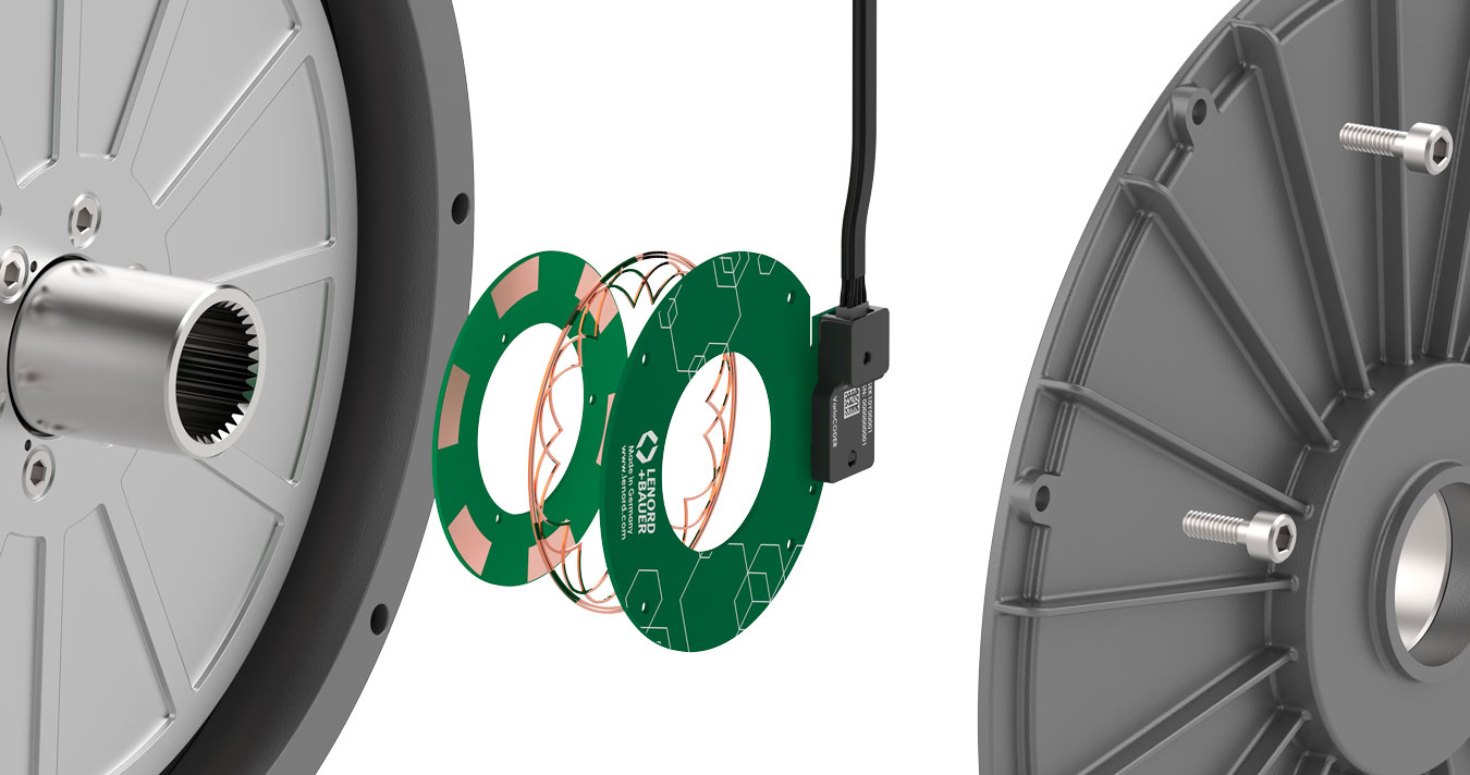
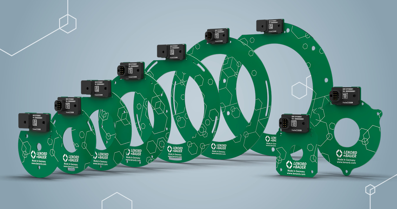
Thanks to their exceptionally flat design and flexibly adaptable geometry, our compact inductive rotor position encoders offer a high degree of design freedom. Whether for shaft-end mounting or as a through-hollow-shaft version – we provide solutions that integrate optimally into a wide variety of drive concepts. Using modern rapid prototyping methods, you receive custom prototype units within a short time, precisely tailored to your requirements.
Precise rotor angles for maximum performance
In motorsport, rotor position encoders are used in electric motors to deliver precise real-time rotor position data. This enables the control system to optimally regulate electric torque – both during acceleration and energy recovery.
The sensors are highly integrated and can be fitted even in very confined installation spaces. Despite extreme temperatures, vibrations, and rapid load changes, they operate reliably and ensure consistent performance of the electric drive.
Inductive rotor position encoders as a resolver alternative in synchronous motors
Inductive rotor position encoders offer a robust, maintenance-free alternative to the resolver. They are more compact, more cost-efficient, and immune to vibration, temperature, and EMI interference.
Their precise, low-latency angle measurement enables efficient FOC control, making them ideally suited for modern synchronous motors and integrated drive systems.
GEL SEK11
Compact inductive rotor position encoder
GEL SEK20
Inductive rotor position encoder, robust
Good to know – quick answers
How is the rotor position detected in a synchronous motor?
Precise rotor position detection is a basic prerequisite for the efficient operation of permanent magnet synchronous machines (PMSM, including BLDC motors). Traditionally, resolvers handle this task. They work inductively, are robust against temperature and vibration, and supply analog sine/cosine signals. A resolver-to-digital converter (RDC) converts these into angle information.
Alternatively, optical or magnetic encoders are used. Inductive position sensors combine the robustness of the resolver with integrated signal processing. They supply the position information directly, either analog or digital, via interfaces such as BiSS-C or SSI, without an external RDC. For traction and industrial applications, Lenord+Bauer offers sensor-based solutions that ensure reliable position detection even under extreme operating conditions.
Why is the rotor position crucial for field-oriented control?
Field-oriented control transforms stator currents into a rotor-fixed (electrical) d/q coordinate system using the Park transformation. Only if the rotor position is known with sufficient accuracy can the torque-producing component (q-axis) and the flux-producing component (d-axis) be controlled independently. Angle errors misalign the current vector relative to the rotor flux. They translate directly into torque ripple, efficiency losses, and potential controller instability.
In highly dynamic applications such as traction, servo, and machine tools, latency and jitter of the position signal are also critical. Modern FOC implementations on DSPs or FPGAs run at sampling rates in the double-digit kilohertz range. This places high demands on sensors and signal conditioning.
Resolver or inductive sensor – which is better for PMSM?
The resolver is regarded as the robust classic: analog sin/cos signals, no active electronics in the sensor head, and high temperature resistance up to about 150 °C. This makes it ideal for traction and aerospace applications. The drawback is the required resolver-to-digital converter (RDC). It increases system complexity and the demands on signal integrity and EMC design.
Modern inductive sensors are increasingly closing this gap. They combine a contactless measuring principle with integrated analog or digital signal processing and supply the absolute rotor position directly via interfaces such as BiSS-C or SSI. This simplifies integration and reduces potential sources of error. For new PMSM developments, the inductive sensor is therefore a technically and economically attractive alternative in many applications, especially with moderate temperature requirements and a high degree of integration.
What accuracy does a rotor position sensor need in a traction drive?
For highly dynamic FOC control in traction drives, electrical angle errors well below 1° should be the target to keep additional torque ripple low. With four to eight pole pairs, this corresponds to mechanical accuracies of about 0.125° to 0.0625°. At the same time, latency and phase delay must stay minimal even at speeds up to 20,000 rpm, so that no additional phase shift arises in the current control loop. Safety functions according to ISO 26262 also require redundant sensor concepts or integrated diagnostic paths.
Manufacturers such as Lenord+Bauer address these requirements with sensors that support ASIL-compliant diagnostics and achieve electrical angle errors below 0.5° over the entire temperature and speed range.